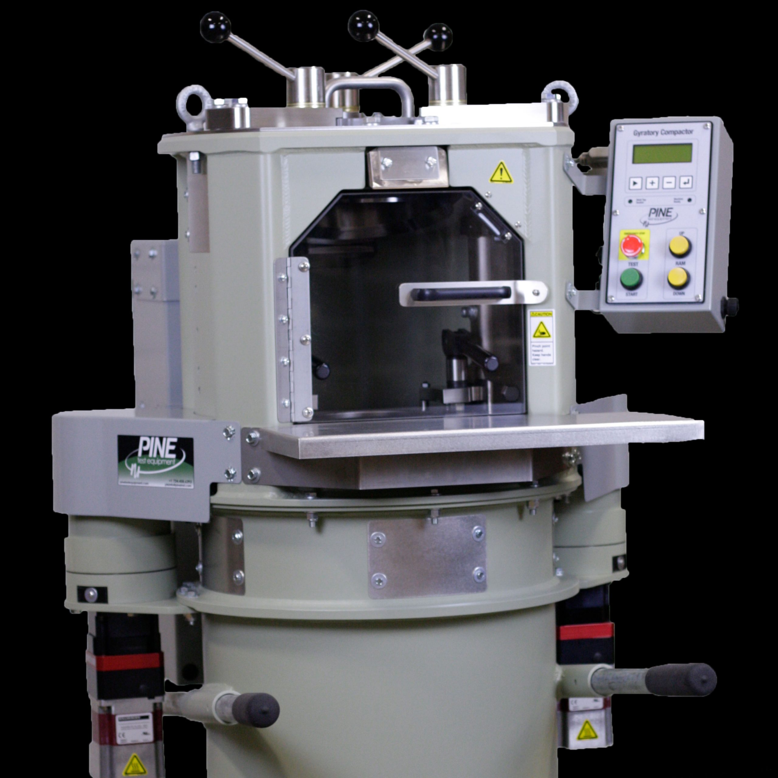
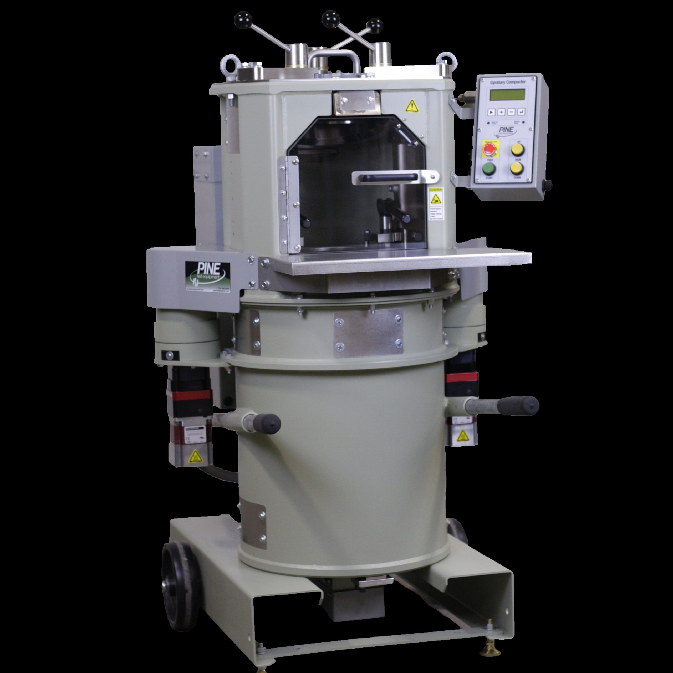
Pine Test Equipment’s G2 Superpave Gyratory Compactor makes asphalt and soil specimens.
The System
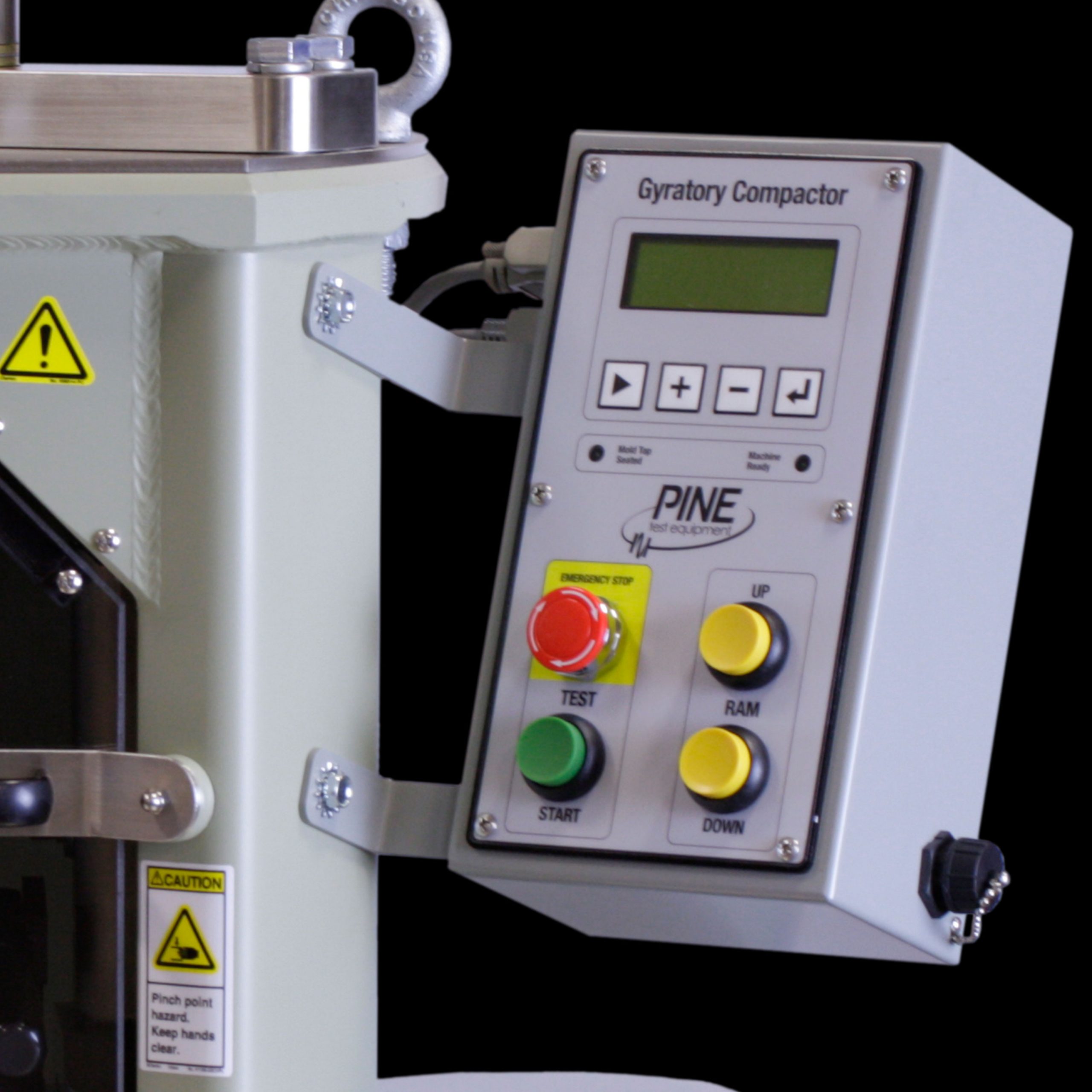
An electromechanical system with integrated controls and angle of gyration measurement drives the G2. Users define compaction mode, specimen size, number of gyrations, target height, pressure, and angle of gyrations using the control panel. The G2 compacts material at a constant pressure and angle of gyration. It gyrates at a fixed speed. An integrated extruder conveniently expels specimens from molds. The enclosed compaction chamber keeps the user safe. And, two USB ports and an Ethernet jack make exporting and printing compaction data easy.
Different Specimen Sizes
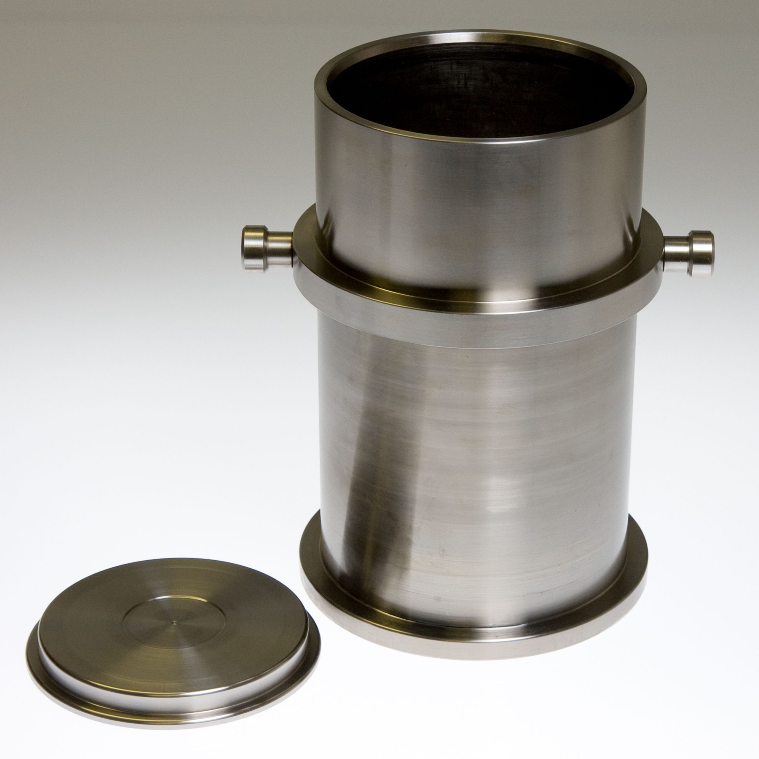
The G2 accommodates 150- and 100-mm specimens. Pine manufactures the standard machine to make 150-mm specimens. However, the 100-mm Conversion Kit along with a 100-mm Mold Assembly allow for the compaction of 100-mm specimens.
Cooling Specimens in Place
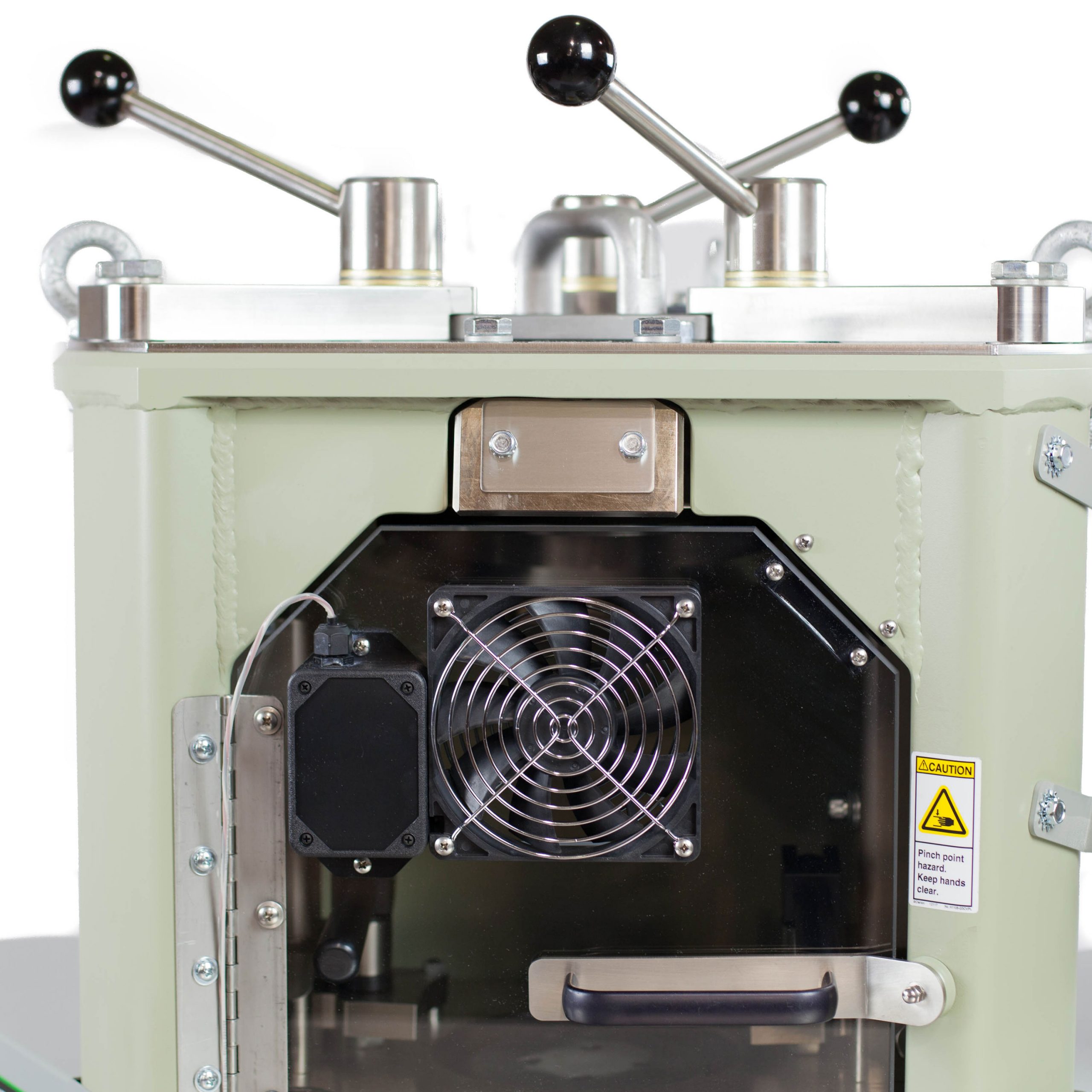
Some asphalt mixes containing rubber expand while cooling if the specimen is not constrained. Holding the specimen in the machine until it cools addresses this problem. Pine provides an optional Cooling Door Kit for the G2. A fan in the door accelerates specimen cooling. And, a shorter cooling time increases potential machine throughput.
Compaction Modes
Pine’s G2 Superpave Gyratory Compactor runs three compaction modes. Number of Gyrations applies a user-defined number of gyrations to the specimen. Compact to Height concludes compaction when a user-defined height is reached. Locking Points stops compaction when the height change between subsequent gyrations is equal to or less than a user-specified height change.
A User Favorite
Customers love the G2 because it is simple to operate, the machine functions consistently, G2’s experience few problems, and Pine supports it well.
Optional Gyratory Shear
Outfit your Pine G2 Superpave Gyratory compactor to measure and record gyratory shear as an optional feature.
Standards/Compliance: AASHTO T 312 ASTM D6925
Operation Manual: Request a Digital Copy
Available Logbook Sheets for Download:
Technical Support and Service:
- Technical support via telephone and email.
- Annual calibration and repair services
G2 and GB1 Product Comparison
Power Requirements:
AFG2A: 115 VAC(±10%), 12 Amp, 50/60 Hz, 1 ph
AFG2B: 208 VAC(±10%), 6 Amp, 50/60 Hz, 1 ph
AFG2C: 230 VAC(±10%), 6 Amp, 50/60 Hz, 1 ph
AFG2D: 100 VAC(±10%), 12 Amp, 50/60 Hz, 1 ph
Dimensions:
875 mm wide x 900 mm deep x 1375 mm high
(~34.5 inch x ~35.5 inch x ~54 inch)
Weight:
Approximately 400 kg (880 lb)
Note: There are three eye-bolts mounted on the top of the machine with which to hoist it.
Applied Pressure:
200 kPa – 1,000 kPa
±60 kPa gyration 0-5; ±10 kPa gyrations >6
Note: Users set the desired pressure via the control panel.
Angle of Gyration:
0.00° – 1.50° (0.00 – 26.18 mrad)
Selectable to internal or external angle
Note: Users set the desired angle of gyration via the control panel.
Speed of Gyration:
30 gyrations per minute
Note: The speed of gyration is fixed.
System:
Electromechanical
Number of Gyrations:
0 – 999 gyrations
Minimum Specimen Height:
0.0 mm
External Mold Dimensions:
215.9 mm OD x 279.4 mm tall
Internal Mold Dimensions (Space Available for Loose Asphalt):
150.0 mm +0.0/-0.1 mm ID x 252 mm tall
100.0 mm +0.0/-0.1 mm ID x 252 mm tall
101.6 mm +0.0/-0.1 mm (4”) ID x 252 mm tall
Note: Molds meet the requirements of AASHTO T312 and ASTM D6925.
Mold Weight (empty):
13.1 kg (29.0 lbs.)
Modes of Operation:
Compact to number of gyrations, specified height, or locking point.
Compact at a specified internal or external angle.
Note: Users set the desired mode of operation.
Data Acquisition:
Gyration number
Specimen height (mm)
Angle of gyration (degrees)
Consolidation pressure (kPa)
Optional – Gyratory tilting moment (N-m)
Data Output Options:
2 USB data ports
Network compatible
Printer (optional)
Part Number
Part Description
RATX90
Digital Stopwatch
Part Number
Part Description
ACG2R29
4-inch Mold Top
AFG2M4
4inch Mold Assembly
AFG2X05
4-inch Conversion Kit
RANLC12
1200-Watt Line Conditioner for 115-VAC machines
RCPUSB
Laser Printer
G2 Operation Manual (Request a digital copy by clicking the part number.)
Part Number
Part Description
RAND10
100-mm Paper Disks (1,000/pack)
Daily
Compaction Chamber
Clean daily.
Clean daily. (Do not use an oven. High temperatures may distort molds making them unusable.)
Monthly
Exercise
Exercise your machine at least once a month to keep parts moving freely if you are not using it otherwise.
25 Hours or Annually
Mold Base Clamps
Check
Ram Drive Belt Tension
The belt has proper tension when there is 0.25 to 0.50 inches of movement in the belt.
Mold Clamps
Look for proper function. An improperly functioning clamp may affect test results.
100 Hours or Annually
Look for wear. Light scoring is expected. Rotate the key to use the unworn end.
Inspect every 100 hours or annually. Look for wear on the outer edge.
Ball Screw Bearings
Apply 2-3 pumps of Bearing Grease (CLGMOS2) into the only grease fitting.
Actuator Bearings
Apply 2-3 pumps of Bearing Grease (CLGMOS2) into the two grease fittings.
500 Hours or 5 Years
Ball Screw
Apply a single bead of Bearing Grease (CLGMOS2) 6” long.
Mold Clamp Pivot
Remove the screws from the swivel frame. Clean thoroughly. Then lubricate with Moly-Grade Anti-Seize Lubricant (CLGSMOS2T).
Mold Top Clamps
Lubricate with Moly-Grade Anti-Seize Lubricant (CLGSMOS2T).
10 Years
Battery
The battery used has a 10-year life.
Videos
Lubrications
What should be considered in identifying a location for a machine?
- A sturdy, approximately level floor is important. The machine weighs about 880 lb. (400 kg) and is top heavy.
- The machine can be installed in a mobile lab. Holes are provided in the lower frame bracket to secure the machine to the floor.
- The minimum floor space requirement is 34.5 inches wide by 35.5 inches deep. Be sure to allow additional space on the right side of the machine for access to the USB data port.
- Allow space on either side of the machine for access to service it when necessary if there is insufficient room to move the machine around for servicing.
- The minimum vertical space necessary is about 54 inches.
- Provide access to an appropriate power supply for the machine purchased.
How movable is the machine?
- The machine comes with a set of wheels and handles installed. Once the machine is off the skid, it can be moved a short distance by a single person. Care must be taken, however, because of the machine’s high center of gravity.
- Three (3) lifting eyes are located on the top of the machine to provide a proper location to connect lifting apparatus.
- The lower frame of the machine is configured to receive fork truck forks.
How often does a machine need calibrated?
- AASHTO R 18 specifies that a gyratory compactor should be verified every 12 months.
- ASTM D6925-15 Section 6.2 specifies that a gyratory compactor should be calibrated annually or whenever there is reason to doubt the stability of the machine’s operation.
- AASHTO R 18 Section 6.2.1.3. specifies that equipment that may be affected by moving it to a new location or environment should be calibrated, standardized, or checked before being placed into service.
- ASTM D6925-15 Section 6.3 specifies that calibration should be verified after it is moved to a new location.
Contact Us
-
Specifications
Power Requirements:
AFG2A: 115 VAC(±10%), 12 Amp, 50/60 Hz, 1 ph
AFG2B: 208 VAC(±10%), 6 Amp, 50/60 Hz, 1 ph
AFG2C: 230 VAC(±10%), 6 Amp, 50/60 Hz, 1 ph
AFG2D: 100 VAC(±10%), 12 Amp, 50/60 Hz, 1 phDimensions:
875 mm wide x 900 mm deep x 1375 mm high
(~34.5 inch x ~35.5 inch x ~54 inch)Weight:
Approximately 400 kg (880 lb)
Note: There are three eye-bolts mounted on the top of the machine with which to hoist it.Applied Pressure:
200 kPa – 1,000 kPa
±60 kPa gyration 0-5; ±10 kPa gyrations >6
Note: Users set the desired pressure via the control panel.Angle of Gyration:
0.00° – 1.50° (0.00 – 26.18 mrad)
Selectable to internal or external angle
Note: Users set the desired angle of gyration via the control panel.Speed of Gyration:
30 gyrations per minute
Note: The speed of gyration is fixed.System:
Electromechanical
Number of Gyrations:
0 – 999 gyrations
Minimum Specimen Height:
0.0 mm
External Mold Dimensions:
215.9 mm OD x 279.4 mm tall
Internal Mold Dimensions (Space Available for Loose Asphalt):
150.0 mm +0.0/-0.1 mm ID x 252 mm tall
100.0 mm +0.0/-0.1 mm ID x 252 mm tall
101.6 mm +0.0/-0.1 mm (4”) ID x 252 mm tall
Note: Molds meet the requirements of AASHTO T312 and ASTM D6925.Mold Weight (empty):
13.1 kg (29.0 lbs.)
Modes of Operation:
Compact to number of gyrations, specified height, or locking point.
Compact at a specified internal or external angle.
Note: Users set the desired mode of operation.Data Acquisition:
Gyration number
Specimen height (mm)
Angle of gyration (degrees)
Consolidation pressure (kPa)
Optional – Gyratory tilting moment (N-m)Data Output Options:
2 USB data ports
Network compatible
Printer (optional) -
Calibration
Part Number
Part Description
RATX90
Digital Stopwatch
-
Accessories
Part Number
Part Description
ACG2R29
4-inch Mold Top
AFG2M4
4inch Mold Assembly
AFG2X05
4-inch Conversion Kit
RANLC12
1200-Watt Line Conditioner for 115-VAC machines
RCPUSB
Laser Printer
G2 Operation Manual (Request a digital copy by clicking the part number.)
-
Consumables
Part Number
Part Description
RAND10
100-mm Paper Disks (1,000/pack)
-
Maintenance
Daily
Compaction Chamber
Clean daily.
Clean daily. (Do not use an oven. High temperatures may distort molds making them unusable.)
Monthly
Exercise
Exercise your machine at least once a month to keep parts moving freely if you are not using it otherwise.
25 Hours or Annually
Mold Base Clamps
Check
Ram Drive Belt Tension
The belt has proper tension when there is 0.25 to 0.50 inches of movement in the belt.
Mold Clamps
Look for proper function. An improperly functioning clamp may affect test results.
100 Hours or Annually
Look for wear. Light scoring is expected. Rotate the key to use the unworn end.
Inspect every 100 hours or annually. Look for wear on the outer edge.
Ball Screw Bearings
Apply 2-3 pumps of Bearing Grease (CLGMOS2) into the only grease fitting.
Actuator Bearings
Apply 2-3 pumps of Bearing Grease (CLGMOS2) into the two grease fittings.
500 Hours or 5 Years
Ball Screw
Apply a single bead of Bearing Grease (CLGMOS2) 6” long.
Mold Clamp Pivot
Remove the screws from the swivel frame. Clean thoroughly. Then lubricate with Moly-Grade Anti-Seize Lubricant (CLGSMOS2T).
Mold Top Clamps
Lubricate with Moly-Grade Anti-Seize Lubricant (CLGSMOS2T).
10 Years
Battery
The battery used has a 10-year life.
Videos
Lubrications
-
FAQs
What should be considered in identifying a location for a machine?
- A sturdy, approximately level floor is important. The machine weighs about 880 lb. (400 kg) and is top heavy.
- The machine can be installed in a mobile lab. Holes are provided in the lower frame bracket to secure the machine to the floor.
- The minimum floor space requirement is 34.5 inches wide by 35.5 inches deep. Be sure to allow additional space on the right side of the machine for access to the USB data port.
- Allow space on either side of the machine for access to service it when necessary if there is insufficient room to move the machine around for servicing.
- The minimum vertical space necessary is about 54 inches.
- Provide access to an appropriate power supply for the machine purchased.
How movable is the machine?
- The machine comes with a set of wheels and handles installed. Once the machine is off the skid, it can be moved a short distance by a single person. Care must be taken, however, because of the machine’s high center of gravity.
- Three (3) lifting eyes are located on the top of the machine to provide a proper location to connect lifting apparatus.
- The lower frame of the machine is configured to receive fork truck forks.
How often does a machine need calibrated?
- AASHTO R 18 specifies that a gyratory compactor should be verified every 12 months.
- ASTM D6925-15 Section 6.2 specifies that a gyratory compactor should be calibrated annually or whenever there is reason to doubt the stability of the machine’s operation.
- AASHTO R 18 Section 6.2.1.3. specifies that equipment that may be affected by moving it to a new location or environment should be calibrated, standardized, or checked before being placed into service.
- ASTM D6925-15 Section 6.3 specifies that calibration should be verified after it is moved to a new location.
-
Contact Us
Contact Us


